A register capable of shifting its binary information either to the right or to the left is called a shift register. The logical configuration of a shift register consists of a chain of flip flops connected in cascade, with the output of one flip flop connected to the input of the next flip flop. All flip flops receive a common clock pulse which causes the shift from one stage to the next.
The logic diagram of a 4-bit serial-in, serial-out, shift-right, shift register is shown in figure. With four stages ie, four FF's, the register can store upto 4 bits of data. Serial data is applied at the D input of the first FF. The Q output of the first FF is connected to the D input of the second FF, the Q output of the second FF is connected to the D input of the third FF and the Q output of the third FF is connected to the D input of the fourth FF. The data is outputted from the Q terminal of the last FF.
When serial data is transferred into a register, each new bit is clocked into the first FF at the positive-going edge of each clock pulse. The bit that was previously stored by the first FF is transferred to the second FF. The bit that was stored by the second FF is transferred to the third FF, and so on. The bit that was stored by the last FF is shifted out.
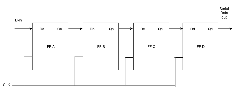
Figure: Logic diagram

Figure: Truth table
We used the following components for this experiment-
After Starting the experiment first click on the Components button to get component list. Now you can Drag and Drop any component in the circuit designing area. To make connection between components, just click on the Blue bubble of any components and Drag it to another Blue bubble of the same or any other components. To delete connection or to remove any component use Double click on that component or connection.
Connect the Vcc and Ground pins of the ICs with the power supply. Now connect the input pins of the ICs with the Input Switches. Connect the output pins with output LEDs. Only pins with Blue bubbles can be used.
Green LEDs are used for indicating logic 0 and Red LEDs are used for logic 1.
After connecting all the required components, click on the Start button.
Q: Convert the following Boolean expression into standard SOP form.
AB'C+A'B'+ABC'D
ANS: Given Boolean expression:
AB'C+A'B'+ABC'D
=AB'C(D+D')+A'B'(C+C')(D+D')+ABC'D (Since X+X'=1)
=AB'CD+AB'CD'+A'B'CD+A'B'CD'+A'B'C'D+A'B'C'D'+ABC'D