
A counter is a sequential circuit that goes through a prescribed sequence of states upon the application of input pulses. The input pulses called count pulses, may be clock pulses, or they may originate from an external source and may occur at prescribed intervals of time or at random.
Synchronous counters are designed in such a way that the clock pulses are applied to the CP inputs of all the flip-flops. The common pulse triggers all the flip-flops simultaneously, rather than one at a time in succesion.
In the 3-bit synchronous counter, we have used three j-k flip-flops. As in the diagram, The J and K inputs of FF0 are connected to HIGH. The inputs J and K of FF1 are connected to the
output of FF0, and the J and K inputs of FF2 are connected to the output of an AND gate, which is fed by the outputs of FF0 and FF1.

>

| FF2 | FF1 | FF0 |
| 0 | 0 | 0 |
| 0 | 0 | 1 |
| 0 | 1 | 0 |
| 0 | 1 | 1 |
| 1 | 0 | 0 |
| 1 | 0 | 1 |
| 1 | 1 | 0 |
| 1 | 1 | 1 |
We used the following components for this experiment-
After Starting the experiment first click on the Components button to get component list. Now you can Drag and Drop any component in the circuit designing area. To make connection between components, just click on the Blue bubble of any components and Drag it to another Blue bubble of the same or any other components. To delete connection or to remove any component use Double click on that component or connection.
After connenting all the required components,click on the Start button and you will get a new start window, where you can give the inputs. After this,you click the run button and finally the outputs are shown.
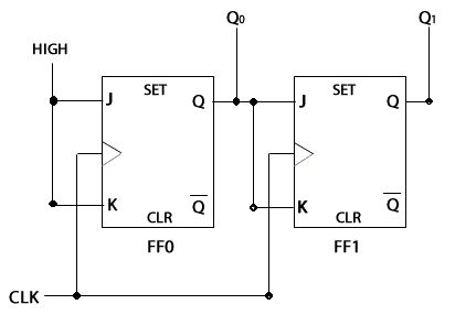
Qn. Design a 2-Bit Synchronous Binary Counter.
Ans: 
In the 2-bit synchronous bnary counter, we have used 2 J-K flip-flops as shown in the above figure. The clock pulse is given to both the flip-flops FF0 and FF1. The J and K inputs of FF0 is connected to the high input. The output of FF0 is connected to the J and K inputs of FF1.